The data plane consists of the VPC data plane and the gateway data plane.
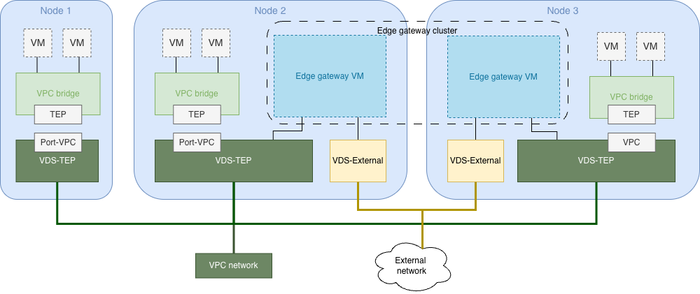
The VPC data plane implements the core functions of VPC, including intra-VPC communication, inter-VPC isolation, VPC subnets, route tables, and security policies.
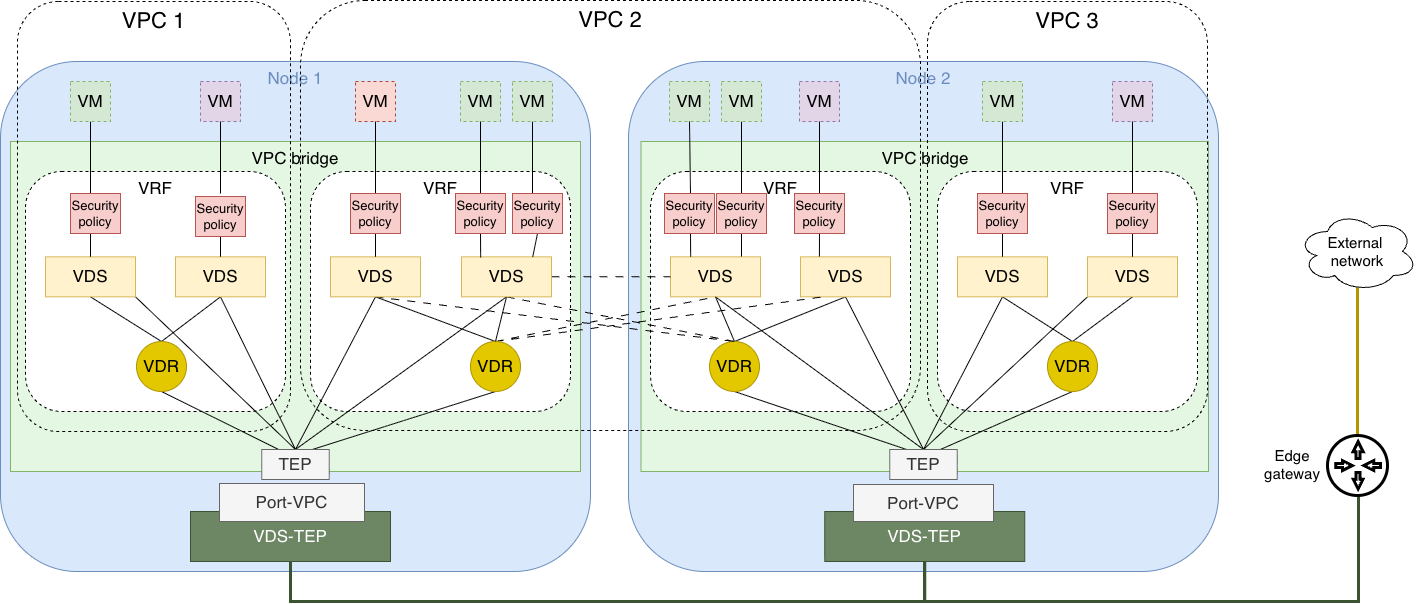
The VPC data plane consists of VPC bridge and VDS-TEP:
VPC bridge: A virtual switch built on OVS bridge that implements VPC network traffic forwarding. It is the core component of the VPC data plane.
VRF: In each node of a cluster associated with VPC networking, each VPC corresponds to one Virtual Routing and Forwarding (VRF) instance, achieving isolation between different VPCs on the same node.
Security policy: Security policies in a VPC apply egress and ingress filtering to packets leaving and entering virtual machines respectively, and support priority configuration so that quarantine policies take precedence.
VDS: The Virtual Distributed Switch (VDS) performs L2 forwarding for packets within a VPC subnet, and forwards packets leaving the VPC subnet to the Virtual Distributed Router (VDR). If the packet's destination address is on another node, the packets are forwarded to the VDS or VDR on the destination node via the TEP port.
VDR: The VDR performs L3 routing for packets leaving VPC subnets, forwarding them to the corresponding VDS or edge gateway. If the destination address is on another node, packets are forwarded to the VDS on the destination node via the TEP port.
TEP port: A GENEVE-type tunnel port that encapsulates and decapsulates GENEVE tunnel packets for cross-node communication. Different VPCs correspond to different Virtual Network Identifiers (VNIs), achieving isolation between different VPCs and between VPCs and the underlay network during cross-node communication.
VDS-TEP interface: A system interface that provides L3 interconnectivity between VPC TEP IPs. It includes the Port-VPC port, which is an OVS port of the internal type. The TEP IP of each node in clusters associated with VPC networking is also configured on this port.
The gateway data plane primarily implements gateway functions for edge gateways, such as floating IP, L2 gateway, routing gateway, and NAT gateway. These functions are implemented using OVS flow tables.
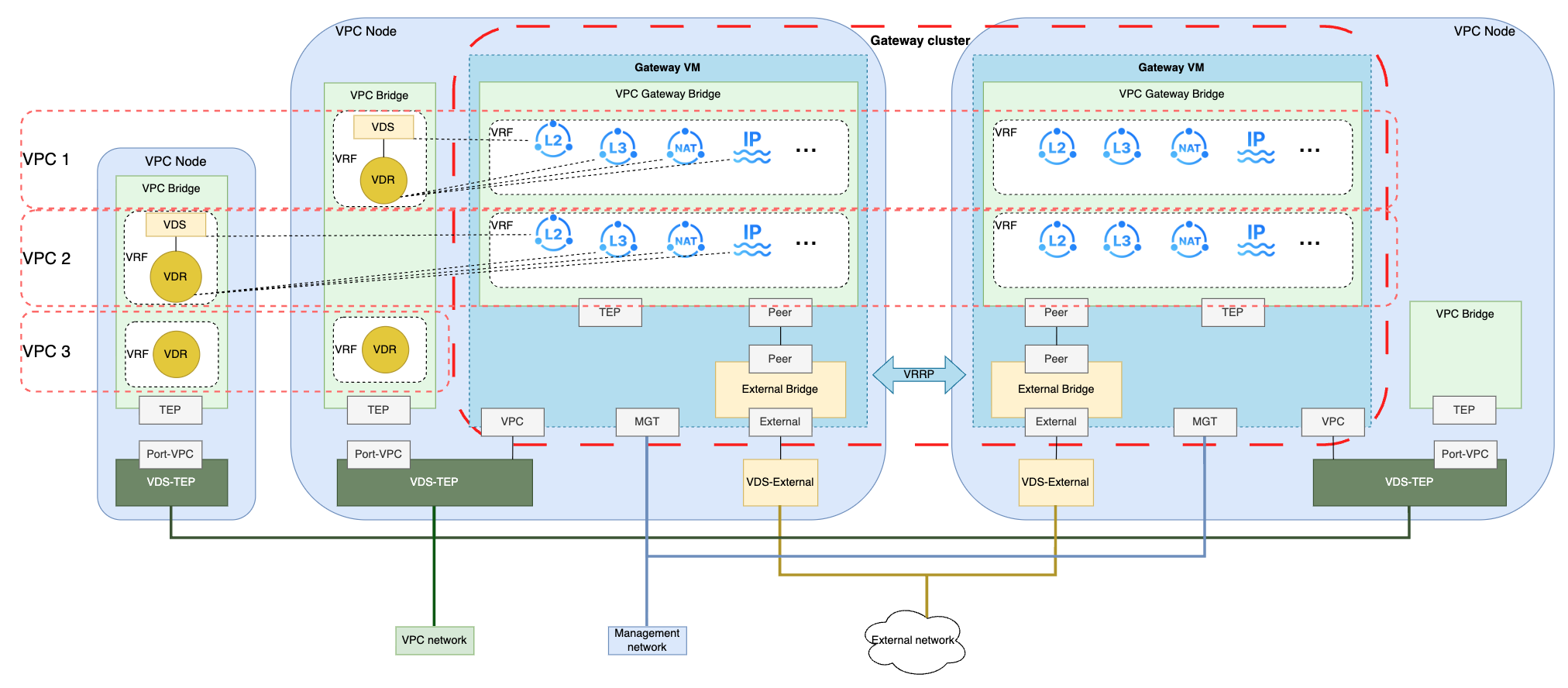
The gateway data plane is deployed in virtual machines. Two edge gateway virtual machines form one edge gateway cluster. Primary-secondary high availability is implemented between the edge gateway virtual machines through a heartbeat mechanism, while conntrackd session synchronization provides hot standby. Each edge gateway virtual machine contains a VPC gateway bridge, an external bridge, and vNICs:
VPC gateway bridge: The virtual switch for the VPC gateway, and the core component of the VPC gateway. It contains the following components:
VRF: In each edge gateway virtual machine, each VPC corresponds to one VRF, achieving isolation between different VPCs on the same edge gateway virtual machine:
Floating IP: Enables L3 communication between IP addresses inside the VPC and external networks.
L2 gateway: Enables L2 communication between VPC subnets and IPs in external networks sharing the same CIDR block.
Routing gateway: Enables L3 communication between VPC subnets and external networks.
NAT gateway: Enables SNAT for VPC network traffic accessing external networks, and DNAT for external network traffic accessing VPC networks.
TEP port: A GENEVE-type OVS port that encapsulates and decapsulates GENEVE tunnel packets when communicating with VPC networks.
Peer port: The port connecting the VPC gateway bridge to the external bridge.
External bridge:
Peer port: The port connecting the external bridge to the VPC gateway bridge.
External port: The port connecting the external bridge to the external NIC.
vNICs:
VPC NIC: The NIC connecting to the VPC TEP network. The TEP IP of the edge gateway virtual machine is also configured on this NIC.
External NIC: The NIC connecting to external networks.
MGT NIC: The NIC connecting to the management network.
