The network configuration of an ACOS cluster with active-active clustering enabled (hereinafter referred to as an "active-active cluster") is basically the same as the network architecture of a common ACOS cluster. However, because an active-active cluster consists of availability zones and a witness node distributed in different regions, you must also configure networks between availability zones and between the availability zones and witness node to ensure connectivity between different regions.
The following is an example topology of an active-active cluster:
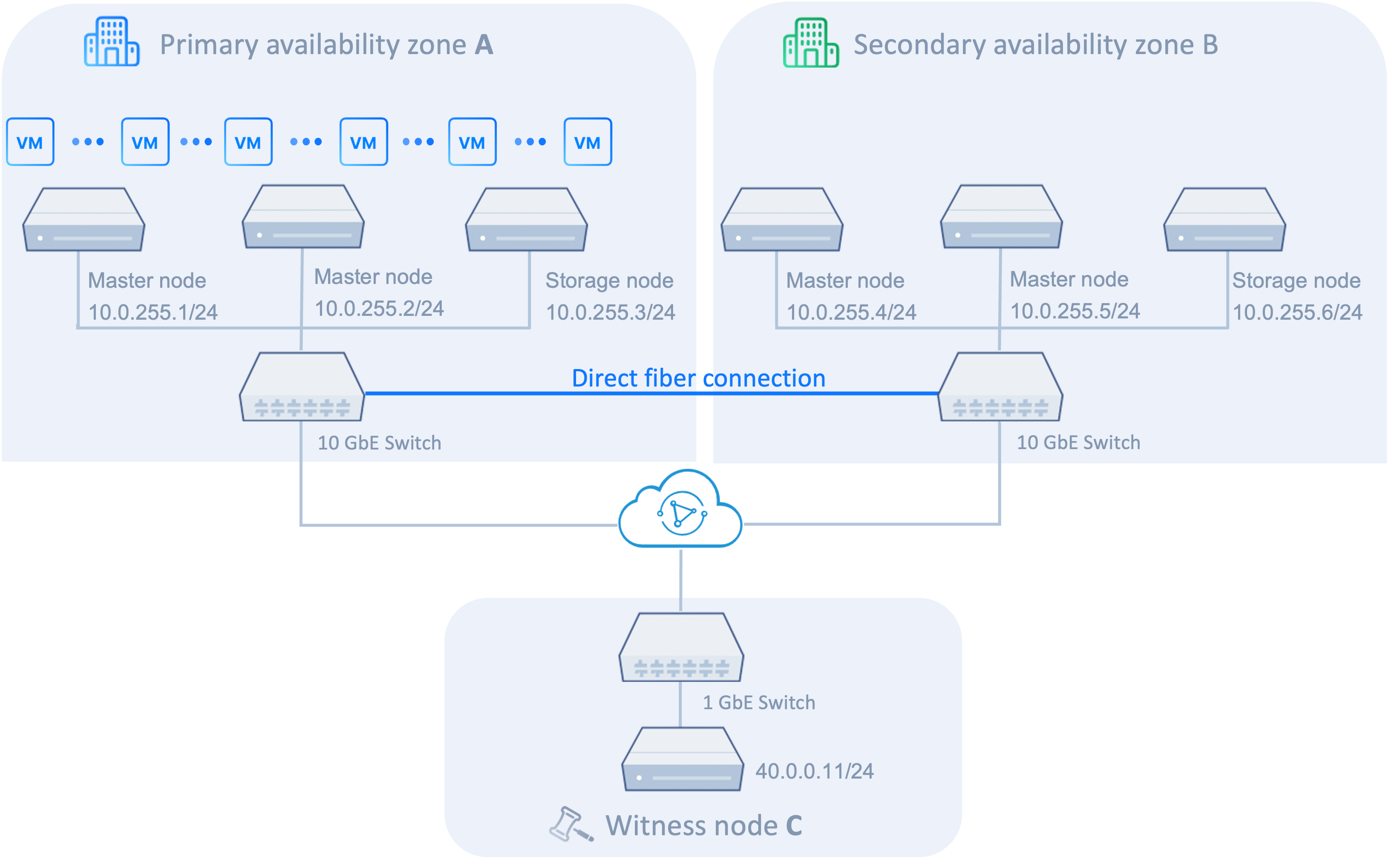
The primary availability zone and secondary availability zone must reside in the same Layer 2 storage network to ensure high-speed service traffic forwarding and low network latency. Therefore, set the storage IP addresses of the primary availability zone and secondary availability zone to the same network segment, and use fiber interconnection. In the topology diagram, for example, the storage networks of primary availability zone A and secondary availability zone B are both in the 10.0.255.0/24 network segment, and the two availability zones use direct fiber connection for Layer 2 network connectivity.
You can configure Layer 2 storage network connectivity or Layer 3 storage network connectivity between the witness node and availability zones. Layer 2 network connectivity provides faster data forwarding and lower network latency. Therefore, Layer 2 storage network connectivity is recommended. If Layer 2 connectivity cannot be implemented, configure Layer 3 storage network connectivity.
When configuring Layer 3 storage network connectivity, configure the storage IP addresses of the primary availability zone and secondary availability zone in the same network segment, and configure the storage IP address of the witness node in another network segment. The IP address of each node and the IP address of its routing gateway must be in the same network segment. Because the witness node and availability zones are in different network segments, configure static routes on the availability zones and witness node to ensure network connectivity.
Using the preceding topology diagram as an example, the network configuration is as follows.
IP configuration
The storage networks of primary availability zone A and secondary availability zone B are configured in the 10.0.255.0/24 network segment. The routing gateway of the primary availability zone is 10.0.255.253, and the routing gateway of the secondary availability zone is 10.0.255.254.
The storage IP address of the witness node is 40.0.0.11. The gateway from the witness node to primary availability zone A is 40.0.0.253, and the routing gateway from the witness node to the IP addresses of the secondary availability zone is 40.0.0.254.
Static route configuration
Configure static routes on the witness node and availability zones to implement bidirectional communication:
Static routes from the primary availability zone to the witness node
| Primary availability zone node | Static route configuration |
|---|---|
| 10.0.255.1/32 | 40.0.0.11/32 via 10.0.255.253 |
| 10.0.255.2/32 | 40.0.0.11/32 via 10.0.255.253 |
| 10.0.255.3/32 | 40.0.0.11/32 via 10.0.255.253 |
Static routes from the secondary availability zone to the witness node
| Secondary availability zone node | Static route configuration |
|---|---|
| 10.0.255.4/32 | 40.0.0.11/32 via 10.0.255.254 |
| 10.0.255.5/32 | 40.0.0.11/32 via 10.0.255.254 |
| 10.0.255.6/32 | 40.0.0.11/32 via 10.0.255.254 |
Static routes from the witness node to the two availability zones
| Witness node | Static route configuration |
|---|---|
| 40.0.0.11/32 | 10.0.255.1/32 via 40.0.0.253 |
| 10.0.255.2/32 via 40.0.0.253 | |
| 10.0.255.3/32 via 40.0.0.253 | |
| 10.0.255.4/32 via 40.0.0.254 | |
| 10.0.255.5/32 via 40.0.0.254 | |
| 10.0.255.6/32 via 40.0.0.254 |
